Wealth Success

SEISA Drive Unit
SEISA COMPOWER Planetary Gear Reducer
SEISA Worm Reducer High-speed Gear Unit
SEISA Industrial Machinery Reducer
SKK Gear Motor
SEISA Coupling
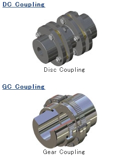
SEISA DC Coupling
SEISA Disc Coupling
SEISA GC Coupling
SEISA Gear Coupling
SEISA SF Coupling
SEISA Grid Coupling
SEISA COMPOWER Planetary Gear Reducer DP1000 Series High-precision rotation spec. COMPOWER Planetary Gear Reducer: DP1000 Series Main features 1. Wide variation of line-up Applicable to various specifications with less number of parts by adopting modular design. Wide selection of Planetary Gear Reducer DP1000 Series for better choice of customer’s requests. 1.Availability of Output Torque from 0.46kNm to 736kNm and Power Range from 0.2kW to 1200kW. 2.Applicable to Reduction Ratio from 1/5 to 1/1400. 3.Applicable to foot mounting, flange mounting and shaft mounting(option). 2. Drive unit Prepared full lineup of direct motor mount type drive units. The unified combination of reducer and basic motor allows simple layout of the equipment. Eliminate the necessity for foundation working for installation and alignment operation. 3.High strength and rigidity of Planetary Gear system 1.Equal distribution of Planetary Gear system. Optimum distribution of load to each gear is secured by Planetary Gear system and structure Slimmer diameter can produce bigger transmission power of torque. 2.High pressure angle gear. 27-degree pressure angle provides higher tooth strength, which is good for shock loads. 27°Pressure Angle 20°Pressure Angle 4.Applications Please refer examples of application from here.
SEISA COMPOWER Planetary Gear Reducer: DP1000 Series High-precision Rotation spec. In response to the growing needs for high-precision rotation reducer, SEISA has developed a new compact model which will satisfy most of clients’ requests including film roll drive and coating equipments. 1.Performance comparison. Rotation Uniformity (angular velocity fluctuation) Note: This table is for the purpose of relative comparison only, and does not assure absolute figures. 2.Compactness. The diameter of COMPOWER is around half of competitor, Planetary TR Drive Unit, which has the same torque. Its compactness realizes the parallel mounting of reducers which was impossible due to the size limit between rolls. 3.Measuring device. Out of several measuring methods, SEISA uses a popular rotation angle detection method by phase difference. The pulse signals of encoders on input shaft and output shaft shall be adjusted to the same frequency, and rotation uniformity will be worked out from the fluctuations of relative phase difference between both signals. 4.Example of measuring record. Rotation Uniformity (angular velocity fluctuation)ε Correlation between angular velocity fluctuation and output shaft angle Output shaft angle[°]
SEISA Worm Reducer Worm reducer Worm Gear Set Double-Lead Worm Gear Set Worm Reducer Any modification of design/production can be made for client’s requirement. Features Double-Lead Worm Gear Set Outline Double-Lead Worm Gear Set is suitable for the operation where the maximum reduction of drive unit allowance is required. It is used mainly for positioning of machine, divider, feed device, coating equipment, etc. About Double-Lead Worm Gear Lead of tooth A of worm is slightly different from that of tooth B of worm. Therefore, the tooth thickness of worm will be uniformly changed according to the difference of lead A and lead B. Tooth-cutting of worm wheel is made in accordance with worm, but every tooth thickness is the same on the circumference. Feature Backlash can be easily adjusted by moving worm toward shaft when fixing backlash at predetermined value in assembling as well as when the level of backlash becomes stronger by the worn-out of tooth face.
SEISA High-speed Gear Units For Generator & Compressor Gas turbine driven drive unit ?Input power 61,000kW 4,997r/min Steam turbine driven reducer ?Input power 40,900kW 6,109r/min Gas turbine driven drive unit ?Input power 61,000kW 5,015r/min Turbo compressor tester ?Input power 10,850kW Motor driven speed-up gear ?Output power 900HP 54,000r/min ?Rim speed 183m/sec (659km/h) Steam turbine driven reducer ?Input power 6,725kW 8,939r/min Motor driven speed-up gear ?Output power 1,350kW 51,851r/min Motor/Steam turbine driven drive unit ?Input power 6,100kW 1,180/18,154r/min Motor driven speed-up gear ?Output power 850kW 13,493r/min
SEISA Industrial Machinery Reducer Any kind of design/production for industrial machinery reducer can be made for client’s operation. For Cement/Coal/Ores Roller mill Ball mill Roller Press Kiln For Plastic/Rubber Twin screw extruder Mixer For Iron/Steel Pinion stand Leveler Press machine Tilting apparatus For Loading/Transportation Winch For Water processing Supply/drainage pump River pump For Generator Wind turbine generator
SEISA DC Coupling Features 1.No need for lubrication Since there is no site of friction or rolling, lubrication is not necessary. 2.Maintenance-free Under the normal operation, only the inspection to loosening bolts and nuts will be necessary. 3.No backlash Because of high rotation uniformity caused by no backlash and strong torsional stiffness, a precise phase control will be secured. 4.High torque transmission By the optimum design, high torque is produced from its compact size. 5.Easy mounting/dismounting As DCP type consists of disk element, bush and washer in a package, connection or removal of coupling can be done easily. 6.High allowable rotation frequency As high-precision bush is inserted between element and bolt, it can be used at extremely higher speed compared with other couplings. 7.Large allowable misalignment Its allowable misalignment is large enough at 0.5~1° in deflection angle and its allowable parallel eccentricity can be adjusted according to the spacer length. 8.Light thrust load As the thrust load generated from coupling is light, burdens of drive shaft and bearings can be extremely minimized . 9.Plentiful inventory DC coupling and its parts are in good stock to be supplied immediately through our sales network.
SEISA GC Coupling Features 1.Torque is fully transmitted even if misalignment of shaft center or vibration occurs. 2.When misalignment or tilt of connected shafts occurs in operation, it will be automatically adjusted. As no extra load is applied to shaft and bearings, machine is well protected. 3.It is a flexible coupling using crowning gear and has high wear resistance and toughness. 4.As it is separated from center case, its assembly and removal are easy. Moreover, as it is compact and light, the mounting space can be minimized. 5.Unlike other types of flexible coupling, misalignment of rotation angle between two shafts caused by deflection of coupling cannot happen. It is suitable for the joint of line-shaft, high-speed usage and heavy-load usage. Features of M Series 1.The shapes are the same as SS/SE/CC/CE types of gear coupling in JIS B1453. In catalog, there are 4 types, which are added “GC” before and“M” after JIS code such as GC-SSM, GC-SEM, GC-CCM and GC-CEM, as well as these other types;GC-SMM, GC-SAM, GC-CAM, GC-MV, GC-SV and GC-EEM. 2.The size number indicates the diameter of coupling case. Bore diameter of shaft is in compliance with JIS, while coupling overall diameter is made more compact. When compared with JIS coupling, therefore, the product is more compact in size and lighter in weight, contributing to your cost savings. 3.As coupling center is longer compared to coupling case width, shafts can be easily aligned by moving the coupling case within the range of boss length. This size also makes the teeth inspection easier. 4.The type GC-SMM for mill motor is in compliance with JEM-1109 standard. 5.Upright types (GC-MV, GC-SV) and spacer types (GC-SAM, GC-CAM) are standardized with the oil seal cover to prevent oil leakage from key way. 6.The type MH, whose transmission capacity is increased by heat treatment, is standardized. 7.The sleeve type GL, which is made more compact, is also available. 8.GC coupling and its parts are in good stock to be supplied immediately through our sales network. The sleeve type GL, which is made more compact, is also available. Types of GC Coupling M Series GC-SSM type GC-SSMH type GC-SEM type GC-SEMH type GC-CCM type GC-CCMH type GC-CEM type GC-CEMH type GC-SMM type Equipped with oil seal cover GC-CMV type GC-CMVH type GC-SMV type GC-SMVH type GC-SV type GC-SAM type GC-CAM type GC-EEM type GC-GL type Construction of GC Coupling 1.Construction GC coupling is constructed by the mesh between internal spur gear of the Coupling Case and crowned external spur gear of the Coupling Center. Having involute tooth profile and special design for top and bottom of the teeth considering tilt and lubrication, it will ensure uniform speed and smooth power transmission even if a slight tilt occurs between Case and Center. Having two gear meshes, GC-SSM and GC-CCM can always keep the Case in the neutral position and transmit power smoothly despite offset alignment, angular misalignment and axial gap. Having single gear mesh, GC-SEM and GC-CEM can accommodate angular misalignment and axial gap. As shown in Figure 5 on page 8 of its catalog, normally two units should be applied in combination using a floating shaft. 2.Major parts and their materials GC-SSM type GC-CEM type GC-SSM type GC-SEM type Part name GC-CCM type GC-CEM type ①Carbon steel Coupling Case Carbon steel ②Carbon steel Coupling Center Carbon steel ③Alloy steel Reamer bolt Alloy steel ④Nitrile rubber ○-ring Nitrile rubber ⑤Alloy steel Oil plug Alloy steel ⑥Carbon steel Rigid Carbon steel ⑦- Side cover General-use steel GC Coupling Flexibility Figure 1 Parallel offset Figure 2 A section shows a gear mesh under offset and angular condition Figure 3 Contact between internal gear and external gear teeth in meshing When offset misalignment exists, the coupling gear tooth tilts by tanφ=δ/L as shown in Figure 1. When the shafts are concentric, the gear tooth is in contact at the crowned tooth center (Ro) as shown in Figure 3(a). However, when the shafts have offset or angular misalignment after installation,the gear tooth comes into contact at the point (R) away from the tooth center as shown in Figure 3(b). The larger the tilting angle is, the remoter point goes away from the center. Thus, the contact on arced surface ensures free and smooth meshing between internal gear and external gear under offset and angular misalignment. Our GC Couplings are designed and manufactured to have adequate crowning and backlash so that they can work freely and smoothly within allowable range. Examples of misalignment a. Parallel offset b. Angular c. Offset + angular d. Axial gap Application Examples Roller table Pump Paper mill Rolling mill Heavy-duty crane
SEISA SF Coupling Features 1.High transmission 1000T Series Tapered Grid is made of high strength alloy steel, is quenched and tempered to spring hardness. The grid surface is then precision shot peened to have residual compressive stress. When a load is placed on the grid, this residual compressive stress negates and controls the compressive force created by the load. The effect is a dramatic increase in rating, providing reserve strength for longer life or allowing a smaller size coupling to be selected. This precision technology was originally used in the production of sophisticated aircraft components. 1000T Series SF Coupling offers positive evidence of leadership in the field of flexible coupling design. Advanced technology is combined with extensive testing and actual field experience. 2.Extended maintenance period After you install the coupling and lubricate it with Long Term Grease (LTG), you can be free from periodic, routine maintenance for quite a long time. LTG(LONG TERM GREASE) General purpose greases commonly break down and deteriorate under the high centrifugal forces encountered in couplings. This effect hastens wear and fatigue. This LTG grease was developed specially for couplings and it resists the separation of the oil and thickening agent that occurs in typical greases. By using LTG grease at the time of installation, you can eliminate routine lubrication cycles unless the lack of lubrication occurs to the tapered grid. 3.Quick installation Single layer tapered grids drop easily into place in a fraction of the time required for straight sided grids. Smaller couplings utilize clearance fits for ease of assembly. Cover assembly is accomplished with standard wrenches. 4.Easy maintenance The grid is a wearing part of SF Coupling, but it is a tiny fraction of the complete coupling cost. Tapered grids are accessible through the quickly removable cover. Removal of the grid is accomplished with a screwdriver or pry bar. The replacement of grids can be done easily by inserting them without the need to move and realign connected equipment as required with gear couplings and many elastomer designs. When coupling connected equipment must be moved, it's work takes longer and costs a lot more, but you don’t worry about it with SF Coupling. 5.Versatile design 1000T Series components are dimensionally interchangeable with the current T series tapered grid SF couplings. Two cover designs, vertical and horizontal, are available in the popular sizes. 6.Plentiful inventory SF coupling and its parts are in good stock in inventory to be supplied immediately through our sales network. Types of SF Coupling Tapered grid T20 type ●Vertically split cover. Ideal for higher running speed. Tapered grid T10 type ●Horizontally split cover. Cover is cast aluminum alloy equivalent to JIS H5302. Ideal for bidirectional operation. Tapered grid T31/T35 type ●Spacer type coupling. Easy mounting/dismounting. Ideal for pump applications. Construction of SF Coupling 1.Tapered grid Tapered grid is made of high strength alloy steel, and is precision shot peened to improve fatigue strength. 2.Cover T20 type is vertically split cover made of steel and T10 type is horizontally split cover made of aluminum. 3.Hub Hub is made of steel with high-precision process and has a specific tooth groove. 4.Seal ring Seal ring is made of strong synthetic rubber and has a wide space for preventing grease leakage or intrusion of water/dust. 5.Locking bolt for cover Locking bolt for cover is made of high-strength steel and prevents loosening together with lock nut. 6.Grease fitting plug Grease fitting plug is attached to cover for easy filling of grease. 7.Gasket Gasket prevents leakage of grease from the matching surface of covers. SF Coupling Flexibility 1.Protection against shaft misalignment The grid is free to rock, pivot and float within the hub teeth. Generous misalignment capacity is provided without producing detrimental bearing side loads created by many elastomer couplings. ●Parallel The movement of the grid in the grooves accommodates parallel misalignment and still permits full functioning of the grid-groove action in damping out shock and vibration. ●Angular Under angular misalignment, the grid groove design permits a rocking and sliding action of the grid and hubs without any loss of power through the resilient grid. ●Axial End float for both driving and driven members is permitted because the grid slides freely in the grooves. End float can also be limited to any required amount by the use of Lang spacer and disk plate. 2.Protection against shock loads, vibration and thrust loads Torsional flexibility is the ability of SF Coupling to torsionally deflect when being subjected to normal, shock or vibratory loads, providing flexible accommodation to changing load conditions. Consequently, SF Coupling is capable of tuning the drive system. It absorbs impact energy by spreading it over an increment of time. It damps vibration and reduces peak or shock loads by as much as 30%. It is a true shock absorber for rotary motion, relying on its specific tooth groove and its predictable resilience of the steel grid for torsional flexibility. As a result, SF Coupling protects drive unit and driven equipment efficiently. ●Light Load The grid bears near the outer edges of the hub teeth. The long span between the points of contact remains free to flex under load variations. ●Normal Load As the load increases, the distance between the contact points on the hub teeth is shortened, but a free span still remains to cushion shock loads. ●Shock Load The coupling is flexible within its rated capacity. Under extreme overloads, the grid bears fully on the hub teeth and transmits full load directly Application Examples Conveyer Centrifugal pump Ski lift Hot strip mill table Paper hoisting machine Cement mill
SEISA Drive Unit
SEISA COMPOWER Planetary Gear Reducer
SEISA Worm Reducer High-speed Gear Unit
SEISA Industrial Machinery Reducer
SKK Gear Motor
SEISA Coupling
SEISA DC Coupling
SEISA Disc Coupling
SEISA GC Coupling
SEISA Gear Coupling
SEISA SF Coupling
SEISA Grid Coupling
